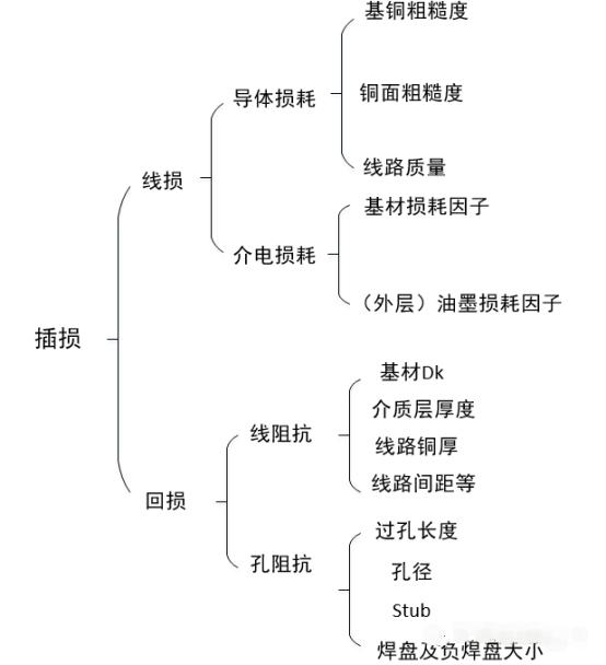
In the previous practice, we developed a high-speed backplane project together with the customer. The customer's loss redundancy space is very limited, and the PCB insertion loss is required to be less than 0.5dB@12.89GHz. This is a very high requirement for both materials and processing. Therefore, before the formal project, we should discuss with the customer to conduct the actual insertion damage test first to see whether the selected material can meet the requirements, and then decide the next step. Now that the test has been completed, we are discussing the next step with the customer. Therefore, I would like to share some of the test results here. Of course, due to the principle of commercial confidentiality, I will deliberately hide the content that may involve the commercial confidentiality clause. Here, first from the processing point of view to talk about my understanding of PCB insertion loss, for the transmission line model without components, to remove the impact of radiation and other design factors, the insertion loss of the transmission line mainly includes two parts, that is, line loss and return loss. Here's a mind map:

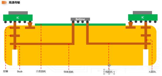
A more clear transmission model can be used to characterize the main factors of loss at the PCB processing end (the main influencing factors of hole impedance at the processing end are layer bias and Stub) as follows:

In summary, the PCB processing end needs to focus on the above factors affecting the loss. Specific processing control details will be elaborated later at a later time. Today I would like to share the content related to this material test.
The Detal-L3.0 plug damage test method was used for this test. Its principle is based on time domain reflectometry (TDR) technology, which uses the reflection phenomenon of electrical signals during transmission in the cable to assess plug damage. It measures and analyzes the transmission loss of the signal in the cable to determine the size of the plug loss. It is designed with two different lengths of transmission lines, through the calculation of different lengths of transmission line insertion loss value difference to calculate the unit length loss of the transmission line, this method can eliminate as far as possible the test fixture and contact emission on the loss test, while eliminating the impact of impedance mismatch, so the insertion loss can be measured here is the line loss. The tedious test process is not described in detail here, but only a few important conclusions are shared: 1. When M7N grade +HVLP3 copper foil is used, the line loss of differential transmission line with 6.5mil line width and 6.5mil medium thickness is about 0.5-0.55dB/inch by conventional processing technology; 2. When the strip copper surface is treated with low roughening solution, the copper surface Rz will be about 1.2um from the conventional 2-5um, and the specific surface area will be reduced from the conventional 50% to < 20%, which can reduce the loss of the same design by about 10%@12.89GHz. 3. When the rotary plate is used and the design is 0°, 5° and 13°, it is not found that the loss changes regularly with the Angle change.